 |
 |
|
|
High-Powered Lenses and ThicknessBy Darryl Meister IntroductionThis course will present the fundamental principles of lens geometry, lens thickness, lens design, and fitting for high-powered lenses, including a review of high-index lens materials, surface geometry, and the optical implications of high-powered lenses. This is a technical, intermediate level course intended for dispensing opticians, laboratory technicians, and paraoptometric personnel. An understanding of both basic mathematics and basic optics is required. Refractive IndexWaves of light travel at a constant velocity of approximately 300,000 km/s in free space. In other transparent media, including lens materials, waves of light will travel at a slower rate. The velocity of light in other media will vary as a function of the refractive index for that material. The refractive index of a transparent medium is essentially a measure of the "optical resistance" of the material to light. It is defined as the ratio of the velocity of light in air compared to the velocity of light in the material: Refractive Index = Velocity in Air ÷ Velocity in Material The refractive index of a material is often abbreviated 'n.' Except for air, which has a refractive index of 1, the refractive index of most substances is greater than 1 (n > 1). Radius of CurvatureBefore we can fully understand the thickness of a lens, we need to understand the geometry of a lens surface. A typical spherical lens surface is simply a section of a sphere. The curvature of a spherical lens surface is dictated by its radius of curvature, which controls how "steep" or "flat" the surface is. The larger the radius of curvature, the flatter the curvature of the surface. Conversely, the shorter the radius of curvature, the steeper the curvature of the surface. For instance, Earth, which has a relatively large radius of curvature, appears quite flat to us as we walk across it. However, a boulder—which has has a much shorter radius of curvature—would appear quite steep to us as we walked across its surface. The radius of curvature of a surface is inversely proportional to its surface power. This means that, as the radius of curvature increases, the surface power decreases. Conversely, as the radius of curvature decreases, the surface power increases. 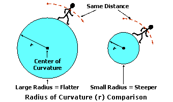 This simply means that steeper surfaces produce stronger surface powers than flatter surfaces. For instance, the radius of a 6.00 diopter surface is twice as long as the radius of a 12.00 diopter surface. The relationship between the power of a surface, in diopters, and its radius of curvature, in meters, is given by: Surface Power = (Refractive Index - 1) ÷ Radius For example, consider a lens surface with an 83.2 mm (0.0832 m) radius of curvature, ground onto hard resin, which has a refractive index of 1.499. The surface power is equal to (1.499 - 1) ÷ 0.0832 = 6.00 D. Surface HeightThe height (or depth) of a convex or concave lens surface is referred to as the sagitta, or simply sag, of that surface. Geometrically speaking, the sagitta (Latin for "arrow") of a curve is the perpendicular distance from the vertex of the curve to some plane cutting through the curve. Consequently, the sagitta of a surface is also known as the vertex depth. The distance (or chord) from one side of the curve to the other across the plane that "cuts" through the curve is associated with the diameter of the lens. For a spherical surface, the sagitta of a lens surface is completely defined by the radius of curvature of the surface at a given diameter (that is, the size of the lens blank). Further, the sagitta of a convex curve is equivalent to the sagitta of a concave curve when the radii of curvature of both surfaces are equal in magnitude. 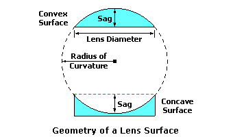 Most eyecare professionals are undoubtedly aware of the fact that the sagitta of a lens surface will vary with both the radius of curvature of the lens surface and its diameter. As the radius of curvature of the surface shortens, the sagitta increases for a given diameter. Since the power of the surface is inversely proportional to its radius of curvature, this means that the height of the surface increases as the power of the surface increases. Further, as the diameter—or size—of the lens blank increases, the height of the surface must also increase. 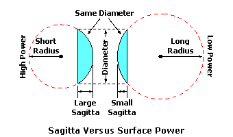 The equation for calculating the exact sagitta (height) of a surface is derived in the Appendix. However, we will use an approximation of this equation, which is simpler to work with—yet still yields answers that are reasonably accurate in most cases. The approximate sagitta of a lens surface, in millimeters, is given by the approximate sagitta formula:
Now that we have examined the relationship between the sagitta of a lens surface, its diameter, and its radius of curvature—which, in turn, is related to its surface power—we can develop a single mathematical relationship between them all. We will combine the approximate formula for the sagitta of a lens surface with the formula for surface power, which will obviate the need to calculate the radius of curvature directly. The approximate sagitta of a lens surface, in millimeters, is therefore also given by:
Note that this equation will yield a negative (-) number for the sagitta of a concave surface—which has a negative (-) surface power. This just serves as an indication that the sagittal value describes a concave surface. From this equation, we can derive several useful rules regarding the height of a lens surface:
The effect of refractive index should not be overlooked. A lens material with a higher refractive index will bend light more for the same amount of curvature. Therefore, a lens material with a higher refractive index requires less curvature to produce the same surface power. In turn, less curvature (i.e., longer radius of curvature) results in a smaller sagitta for a given lens diameter. This means that high-index materials will produce shallower lens surfaces for the amount of surface power. For example, consider the previous lens surface with a 6.00 D curve, ground into hard resin (index = 1.499), at a diameter of 60 mm. The approximate sagitta is equal to (½ Diameter)2 · Surface Power / [2000 · (Index - 1)] = (½ 60)2 · 6.00 / [2000 · (1.499 - 1)] = 5400 / 998 = 5.4 mm. In this example, the actual sagitta is 5.6 mm, which means that the approximation is quite accurate—within 5% of the actual value. However, as the diameter increases or as the radius of curvature decreases, this approximation will begin to lose accuracy. Lens GeometryA lens is little more than two surfaces in a lens material separated by a finite amount of center or edge thickness. Note that "center" in these cases refers to the optical center of the lens, which is the point of zero prismatic effect. The power of each surface contributes to the total focal power of the lens. In fact, the total focal power of the lens, which is the capacity of a lens to add either convergence or divergence to incident waves of light, is simply the net effect of its two surfaces. The focal power of a lens, in diopters, is therefore given very nearly by: Focal Power = Front Surface Power + Back Surface Power Modern ophthalmic lenses are generally meniscus—or "crescent-shaped"—in form. This means that they typically have a convex front surface (i.e., positive power) and a concave back surface (i.e., negative power). Because focal power is the net effect of both surfaces, you can make three general statements concerning the relationship between the front and back surfaces and the thickness of the lens:
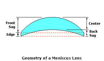 Since the thinnest point on a plus lens occurs at the edge, the edge thickness of a plus lens represents its minimum thickness. Conversely, the thickest point on a plus lens occurs at the center, which represents its maximum thickness lens. The center thickness is given by: Center Thickness = Edge Thickness + (Front Sagitta + Back Sagitta) Recall that, consistent with our earlier sign convention, concave surfaces have negative (-) sagittal values. Since the thinnest point on a minus lens occurs at the center, the center thickness of a minus lens represents its minimum thickness. Conversely, the thinnest point on a minus lens occurs at the edge, which represents its maximum thickness lens. The edge thickness is given by: Edge Thickness = Center Thickness - (Front Sagitta + Back Sagitta) Note that the highest surface of a minus lens is concave, which has a negative (-) value by convention, so the sum of the front and back sagittal values is also negative. However, since this negative sum is actually subtracted from the center thickness in this equation, the edge thickness value is still positive. 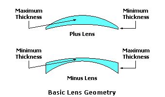 The previous two equations are used to find the maximum thickness of the lens based upon both the minimum thickness and the sum of the front and back sagittal values. By considering only the magnitude, or absolute value, of the sum of the front and back sagittal values by ignoring the sign of the answer, we can express these two equations using a single formula: Maximum Thickness = Minimum Thickness + |Front Sagitta + Back Sagitta| (The absolute value of a number, denoted by the || symbols, ignores the minus sign for negative numbers.) Keep in mind that minus lenses are never made to a "zero" center thickness, and plus lenses are very seldom surfaced to a "zero"—or knife-edged—edge thickness. There is always some minimum substance or thickness to the lens. Typical minimum thickness guidelines for traditional ophthalmic lenses range from a minimum edge thickness of 1 mm to a minimum center thickness of 2 mm. The manufacturer's minimum thickness guidelines ensure that the lens will have enough thickness to provide sufficient impact resistance for eye protection and sufficient flexural stability while processing. Most minus lenses will be either surfaced to or supplied in finished form with centers between 1.0 mm and 2.2 mm, depending upon the power of the lens, type of lens material, and lens design. Certain lens materials, such as polycarbonate, have a relatively high tensile strength and satisfy the FDA's impact-resistance requirement even with thinner centers. Additionally, in some cases, the manufacturer may apply an impact absorbing primer coating in order to allow for thinner centers. However, lenses intended for rimless or safety frames may be supplied with a greater center thickness. Calculating Lens ThicknessRecall that the maximum thickness represents the center thickness of plus lenses and the edge thickness of minus lenses. Now that we have a mathematical description of the maximum thickness of a lens, we can substitute our approximate sagitta formula for the front and back sagittal values. The maximum thickness of a lens, in millimeters, is given by: Maximum Thickness = Minimum Thickness + |Front Sagitta + Back Sagitta| Now, we can substitute our approximate sagitta formula for the front and back sagittal terms. This allows us to express the equation in terms of surface powers, which gives us the following expression for the quantity |Front Sagitta + Back Sagitta|:
Which, after rearranging, gives us the expression:
And, since the sum of the front surface power and back surface power is equal to the total focal power of the lens, we finally arrive at one simple equation for the maximum thickness of both plus and minus lenses:
This provides us with a relatively simple equation for calculating the approximate maximum thickness of a lens. Note that the absolute value of the focal power is used in this equation, which means that the negative (-) sign for minus lens powers should be ignored. Of course, the actual thickness of the lens will vary slightly, since this equation is based on the approximate sagitta of each surface. When accuracy is critical, the exact sagitta formula should be used to calculate thickness (see Appendix). Essentially, we are treating the meniscus lens as a simpler, flat lens—with one flat or plano surface and one concave or convex surface whose power represents the total focal power of the lens. This treats a plus lens as a simple plano-convex with the front surface equal to the power of the lens and a minus lens as a simple plano-concave lens. This approach has the added advantage that neither the front nor back surface needs to be known, since only the power of the lens is used in the calculation. 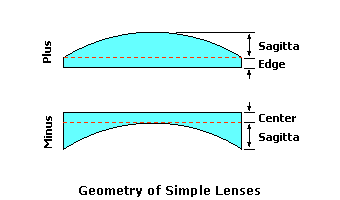 As with the approximate sagitta formula, this equation for lens thickness demonstrates several important relationships between the thickness of a lens, the focal power of the lens, the refractive index of the lens material, and the diameter of the lens blank:
We can solve this approximate equation for various values of the diameter and the refractive index in advance. A table of such constants, which we will call thickness factors, can be prepared and kept readily available. These thickness factors represent millimeters of thickness per diopter of power for a given lens size and refractive index. To approximate the maximum thickness for a given refractive index and diameter, we can simply multiply the appropriate thickness factor by the power of the lens, and then add any minimum thickness: Maximum Thickness = Minimum Thicknes + Thickness Factor × |Power|
For example, consider a -4.00 D hard resin lens edged to a diameter of 60 mm with a center thickness of 2 mm. Hard resin has a thickness factor of 0.90 mm per diopter at a diameter of 60 mm. This gives us a maximum (edge) thickness of 0.90 × 4.00 = 3.6 mm. After adding the minimum center thickness, we have a total edge thickness of 3.6 + 2.0 = 5.6 mm. Minimum Blank SizeIn order to determine the thickness of a lens we need to know at least the focal power of the lens and the diameter of the lens blank. Of course, the power of the lens is a given, since it is specified by the prescription. And, up to this point, we have assumed a lens diameter (size). However, if the diameter is unknown, a few more computations may be necessary, especially for minus lenses. It is important to note that the center thickness of a finished lens is fixed with respect to the initial diameter of the lens blank. Once cast by the lens manufacturer in the case of factory-finished (or "stock") lenses, or processed to the desired power by the surfacing laboratory in the case of semi-finished (or "surfaced") lens blanks, the center thickness of the lens is permanently established. This has several important consequences for lens thickness:
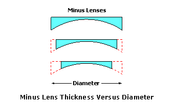 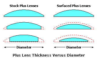 The smallest circle, centered at the geometric center (GC) of a frame, that completely encircles the aperture (or opening) of the frame is known as the effective diameter (ED) of the frame. The effective diameter of the frame is equal to twice its effective radius (ER), which is the distance from the geometric center of the frame to the farthest point along the perimeter—or eyewire—of the frame. The smallest possible lens diameter that will cut-out for a given Rx job—including frame style and fitting measurements—is known as the minimum blank size. In the case of single vision lenses, this represents the size of the lens blank required to completely cover the aperture (opening) of the frame after the lens has been decentered to the wearer's interpupillary distance (PD). Decentration is the horizontal displacement of the optical center of the lens from the geometric center of the frame in order to position the optical center in front of the wearer's line of sight. If the lens requires no decentration, the minimum blank size of the lens is equal to the effective diameter of the frame. Otherwise, the minimum blank size is equal to twice the new effective radius of the decentered lens, which is the distance from the newly positioned optical center of the lens to the farthest point along the perimeter (eyewire) of the frame. 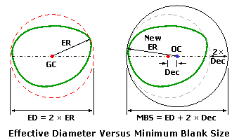 Determining the exact minimum blank size is difficult to do, since it requires calculating the maximum distance from the optical center of the lens to the perimeter of the frame. However, if we assume the "worst case scenario"—that is, if we assume that the decentration occurs along the meridian of the frame containing the effective diameter—we can arrive at a simple rule-of-thumb formula for determining the minimum blank size of a decentered lens. This rule-of-thumb formula is known as the minimum blank size formula: Minimum Blank Size = Effective Diameter + 2 × Decentration Because this formula assumes the "worst case," the minimum blank size of a single vision lens will never be larger than the blank size predicted by this equation. Consequently, using this formula will always err on the side of caution. Additionally, certain prescription combinations—such as plus prescriptions with minus cylinder power—may necessitate even smaller minimum blank sizes at certain cylinder axis angles, though this consideration is beyond the scope of this article. If this formula is used to determine the minimum blank size for edging purposes, an additional allowance of 1 to 2 mm should made in order to account for the bevel. Frame Shape and Blank SizeAs described earlier, the minimum blank size for a given job will vary with the decentration required. Since thickness increases rapidly with the minimum blank size, XXX. Therefore, when lens thickness is a consideration, it is important to select a frame that minimizes decentration as much as possible. If the decentration is not already known, it can be calculated from the eyesize (or "A" measurement), bridge size (or "DBL"), and the wearer's interpupillary distance (PD) using: Decentration = (Eyesize + Bridge Size - PD) ÷ 2 For minus lenses For plus lenses, While the maximum thickness , the thickness of a plus lens XXX. COnseqeutnly, it . 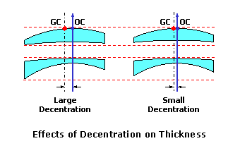 The shape of the frame will also impact the minimum blank size needed for a given job. Two frames with identical A (eyesize) and B (depth) measurements can have very different effective diameters. Frames with exotic shapes—such as "harlequin" or "aviator" styles—often require larger minimum blank sizes than round or oval frame styles. The meridian of the effective diameter (or twice the distance from the center of the frame to the farthest point along its perimeter) with exotic frame shapes often occurs, which XXX. 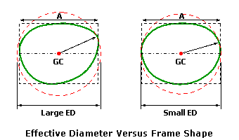 Cylinder Power and ThicknessWhen a prescription calls for cylinder power, the curvature and power of the lens varies from meridian to meridian. For a lens made in minus cylinder form, which is usually the case, this also means that the edge thickness of the uncut lens varies from meridian to meridian. When the cylinder power of a prescription is significant, the contribution of cylinder power to edge thickness should be considered, particularly for minus lenses. 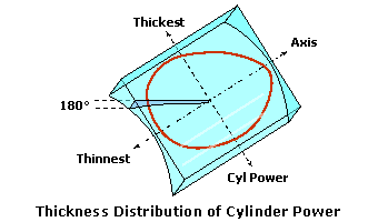 The meridian associated with the axis of the prescription contains only the sphere power, and there is zero cylinder power along this meridian. In the absence of prism, the thinnest points along the edge of an uncut lens will occur at this meridian. Away from this meridian, the contribution of the cylinder power to the total power through any meridian begins to increase—in a sinusoidal fashion. At 90° from the axis of the prescription, the total power contains the maximum cylinder power, so that the total power is equal to the sum of the sphere and cylinder power. The thickest points along the edge of an uncut lens will occur at this meridian. Consequently, the edge thickness of a minus lens through any particular meridian is due to both the sphere power and the contribution of the cylinder power through that particular meridian. For a typical frame shape at least, the edge thickness of the lens generally reaches its maximum along the horizontal (180°) meridian, since the distance from the optical center to the perimeter of the frame (or the effective radius) is greatest near this meridian after decentration. Therefore, we are typically interested in finding the contribution of cylinder power along the horizontal meridian. Mathematically, the total power along the horizontal meridian can be calculated using the sine-squared rule: Horizontal Power = Sphere Power + Cylinder Power × sin2 Axis For example, consider a prescription of -1.00 DS -1.50 DC × 045. The total power along the horizontal meridian is equal to -1.00 + (-1.50) × sin2 45 = -1.75 D. When axis of the prescription is close to 180, the power through the horizontal meridian is roughly equal to the sphere power. When the axis is close to 90, the power through the horizontal meridian is roughly equal to the sum of the sphere and cylinder power. A table of results appears below.
Lens Form and ThicknessAlthough it is not apparent from the use of our approximate lens thickness formula, the maximum thickness of a lens—for a given prescription—actually varies with the form of a lens. Since the sagitta (height) of a lens surface increases more rapidly than its surface power, the maximum thickness of the lens for a given focal power increases as the surfaces become steeper. Consequently, flatter lens forms—with shallower curves—are slightly thinner than steeper lens forms. Since the lenses are thinner, they also have less mass—making them lighter in weight as well. 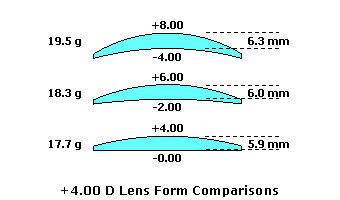 In addition to lens thickness, varying the lens form will also produce significant differences in the plate height, or overall bulge, between lenses of the same power. Essentially, plate height is the height of a lens as measured from a flat plane. Plus lenses with flatter plate heights do not fall out of frames as easily, which is especially important with large or exotic frame shapes. In addition, flatter plate heights are also more cosmetically pleasing than steeper, bulbous ones—particularly in plus powers. 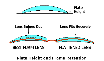 A reduction in plate height will also provide a significant reduction in the magnification associated with plus lenses. Since a flatter plate height brings the back surface closer to the eye, the minification associated with minus lenses is also reduced slightly. This gives the wearer's eyes a more natural appearance through the lenses. We can evaluate the maximum thickness, plate height, and weight for a range of lens forms to demonstrate the effects of lens form upon cosmesis for a given prescription. The table, below, represents a range of +4.00 D lenses in hard resin plastic, edged to a 70-mm diameter and a 1-mm minimum edge thickness.
Note how the lenses become gradually thinner, flatter, and lighter in weight as the base curve is reduced—or flattened. Minimizing Lens Thickness
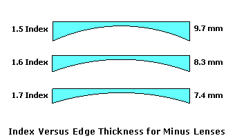 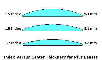 Because the maximum edge thickness of a minus lens is more obvious to the wearer (and others) than the maximum center thickness of a plus lens, myopes (nearsighted wearers) are often more concerned with lens thickness. Therefore, it is especially helpful to have a strategy in place for estimating and minimizing edge thickness for minus lenses. Using the principles presented earlier, there are four basic steps for estimating the approximate edge thickness of a minus lens:
RULE OF THUMB THICKNESS REDUCTION BY INDEX High-Index MaterialsWhen dispensing lenses of moderate to high power, "high-index" lens materials are often utilized to minimize lens thickness and weight. There are three properties of lens materials that are especially relevant in the context of high-powered lenses:
When the refractive index of a lens material is greater than the standard tooling index of 1.530, the material is often referred to as a high-index material. In some cases, however, lens materials may be further categorized as follows:
The refractive index of a lens material is actually due to the refractivity of the individual elements that constitute the molecules of the material. The "atomic refractivity" of different elements varies significantly. The primary elements that form the molecules of polymer plastics include carbon, hydrogen, and oxygen, which have relatively low refractivity. Some elements, however, have a high refractivity, including sulfur and the various metals. It therefore becomes possible to increase the overall refractive index of a lens material by adding such elements to the molecules that make up the material. Sulfur and various aromatic structures are commonly used to increase the refractive index of polymer plastics. Common "high-index" plastic materials are often made from various forms of polyurethane, which is a cross-linked thermosetting resin that generally has a good combination of tensile strength and surface hardness. MR-7, a common high-index plastic material with a refractive index of 1.66 to 1.67, has 30% sulfur content. MR-174, a newer high-index plastic material with a refractive index of 1.73 to 1.74, has 60% sulfur content. Unfortunately, there are limits on the amount of sulfur that can be added to the material. Increasing the refractive index of a polymer plastic beyond 1.80 will most likely require the addition of metal elements to the molecules of the material. Several "mid-index" materials are also made from acrylic, which may be either thermoplastic or thermosetting (cross-linked) and may also be combined with urethane. Mid-index materials, which frequently have a refractive index between 1.53 and 1.56, typically have a higher Abbe value than high-index materials. Another extremely popular lens material is polycarbonate, which is a thermoplastic resin that demonstrates an extremely high tensile strength for excellent impact impact resistance. Polycarbonate has a refractive index of 1.59 (1.586) and a very low density (1.20). Crown glass is an amorphous (non-crystalline) material made primarily of quartz sand (silicon), soda, and lime. High-index glass materials are generally produced by adding various metal oxides with a higher atomic refractivity to the composition of the glass, including lead (used in early flint glass bifocal segments), titanium, and lanthanum. However, the addition of these metals typically increases the density of the material. Ophthalmic glass is currently available in refractive indices up to 1.90. The higher the refractive index of a lens material, the slower the light will travel through it. In reality, the refractive index of any material varies slightly as a function of the wavelength (color). This means that various colors of light will each actually have a slightly different refractive index in the same lens material! This phenomenon is responsible for chromatic dispersion, or the breaking up of white light into its component colors by prisms and lenses. Blue light, which has a higher refractive index than red light, is therefore refracted—or bent—more than red light as it passes through a lens or prism. The degree to which a given lens material will disperse light is described by a measure of its refractive efficiency or, more commonly, its Abbe value (after Ernst Abbe). It is also referred to as constringence. Lenses with a high Abbe value will disperse light less than lenses with low Abbe values. In general, high-index materials produce lower Abbe values than conventional plastic and crown glass lens materials, which makes these materials more likely to produce symptoms of chromatic aberration. Furthermore, the higher the refractive index of the material, the lower the Abbe value is likey to be. 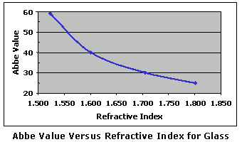 The weight of a lens material is determined by its density, which is the mass of the material per unit volume (generally measured in grams per cubic centimeter, or g/cc). The lower the density, the lighter the material will be for a given volume. (For spectacle lenses, the volume depends on the size and thickness of the lens.) Another term frequently used is specific gravity, which is the ratio of the mass of a material or liquid compared to the mass of an equal volume of water (at 4°C). When measured in g/cc, density is synonymous with specific gravity since a gram is equal to one cubic centimeter of water. The properties of some common lens materials are listed below.
Aspheric Lens DesignsThe use of special, non-spherical surfaces, referred to as aspheric surfaces, allows lens designers to flatten a lens form in order to improve cosmesis, without sacrificing opical performance. Flattening the form of a lens with a spherical base curve from traditional "best form" recommendations will result in significant optical errors—or lens aberrations—in the periphery of the lens, including oblique astigmatism. However, the lens aberrations produced by using flattened lens forms are neutralized by the surface astigmatism of the aspheric design. While aspheric lenses do not necessarily provide better vision than traditional lenses in lower powers, they do provide equivalent vision in a flatter, thinner, and lighter lens. However, in high plus prescriptions—above roughly +8.00 D—aspheric lens designs can provide considerably better vision than spherical base curves in any form. 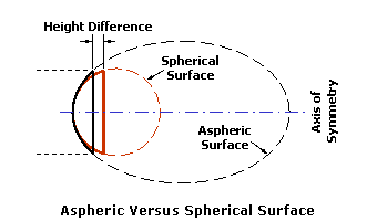 Aspheric lenses allow lens designers to produce lenses that are considerably flatter, thinner, and lighter in weight than conventional (i.e., "best form") lenses. Aspheric surfaces produce thinner lenses for two reasons:
Ideally, aspheric lenses should be optimized for each individual focal power. In practice, however, small ranges of powers are grouped upon common aspheric base curves—just like with best form lenses. Nevertheless, asphericity gives lens designers the freedom to optimize just about any base (front) curve for the chosen focal power—or range of powers. (Generally, flatter base curves are chosen for cosmesis.) 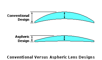 Aspheric base curves free lens designers from the constraints of conventional (best form) lenses—which use simple spherical base curves. Lenses can be made flatter, thinner, and lighter, while maintaining the same excellent optical performance. Moreover, aspheric lenses are essential in high plus prescriptions, since traditional spherical lens designs cannot eliminate lens aberrations in this prescription range. The table, below, represents a comparison of lens designs for a +4.00 D prescription in hard resin plastic, edged to a 70-mm diameter and a 1-mm minimum edge thickness. Note that the best form lens design provides good peripheral optics (that is, very little oblique astigmatism off-center), while the flattened lens design (that is, made using a flatter base curve) provides a thinner, lighter, and flatter profile with poor optics. Finally, the aspheric lens design provides both good optics and the thinnest, lightest, and flattest lens profile.
High-Powered LensesAs the power of a spectacle lens increases, the optical and mechanical issues associated with lens power also increase. For prescription powers stronger than ±4.00 diopters, the fit and design of the lens become especialy critical due to the sensitivity of these higher powers to changes in lens design or position. This means that great care must be taken when fitting and dispensing high-powered lenses in order to ensure maximum optical performance and visual comfort for the wearer. The following factors should be considered when fitting and dispensing high-powered lenses lenses:
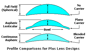 Because of differences in magnification and thickness, plus-powered lenses and minus-powered lenses each present unique optical and mechanical challenges. Special lens designs have been devised to address the optical and mechanical requirements specific to high plus lenses and to high minus lenses. High Plus Lens DesignsMany dispensers have come to rely on high-index lens materials as the only option for minimizing lens thickness. For low to moderate plus powers, center thickness and weight can generally be controlled satisfactorily using high-index materials, aspheric lens designs, and sensible frame styles. However, for higher plus powers, particularly those for post-operative cataract patients with no crystalline lenses, more radical lens designs may be necessary to control thickness and weight adequately. Indeed, for extremely high-powered plus lenses, it may not be possible to fabricate a lens blank beyond 50 to 60 mm in diameter using conventional designs. Moreover, while high-index lens materials can afford some reduction in thickness, the effects of chromatic aberration may become intolerable to the wearer for these prescriptions. However, significant thickness reduction can be obtained by using alternative plus lens designs. Common lens designs for high-powered plus lenses, beyond +8.00 or +9.00 D—which are often referred to as cataract lenses, include:
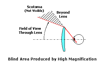 Another optical issue characteristic of high-powered plus lenses is the annular blind area, or scotoma, that is produced in the wearer's periphery. Because of the high magnification produced by plus lenses, the field of view through the lens is relatively narrow. Consequently, there is a blind area surrounding the periphery of the lens between the field of view through the lens and the object field immediately visible outside the lens edge (or bowl, in the case of lenticulars). This also results in a somewhat startling "jack-in-the-box" effect for the wearer as objects pass through the scotoma and suddenly reappear on the other side it. 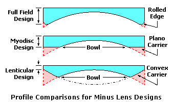 Since the advent of intraocular lens implants, which are artificial crystalline lens implants, high-powered "cataract" lens designs have become relatively scarce. However, several cataract lens design options are still available through a handful of manufacturers. High Minus Lens DesignsAs with plus powers, for low to moderate minus powers, edge thickness and weight can generally be controlled satisfactorily using high-index materials, aspheric lens designs, and sensible frame styles. Again, for higher minus powers, more radical lens designs may be necessary to control thickness and weight adequately. For instance, it may not even be possible to close the temples completely on a frame with a pair of -10.00 D lenses because of the excessive edge thickness. The wearer should be made aware of other options in these cases, particularly if he or she has expressed concern over the thickness of previous eyewear. Further, as with high plus prescriptions, the effects of chromatic aberration must also be considered. However, significant thickness reduction can again be obtained by using alternative minus lens designs. Common lens designs for high-powered minus lenses include:
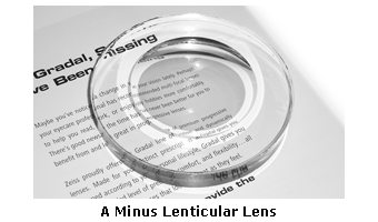 Aspheric lenticulars and other high plus lens designs employ special surfaces that must be fabricated using specialized manufacturing equipment and molds. However, high minus lens designs can be fabricated using traditional surfacing equipment, though this of course involves a great deal of skill. The image, below, is a photo of a minus lenticular lens. Note the difference in size between the letters that appear through the carrier region versus those that appear through the central bowl region. 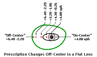 To overcome the cosmetic issues surrounding the bowl of these specialty designs, one manufacturer (Younger Optical) introduced a blended lenticular design, referred to as a Blended Myodisc. The edge of the bowl in this design has been smoothed and blended into the carrier, making the demarcation between the carrier and the bowl virtually invisible. The blended surface of these designs is also molded by the manufacturer, instead of being surfaced by the laboratory, which simplifies the processing greatly. For extremely high minus powers, the Blended Myodisc design should certainly be considered. Lens AberrationsWe've just discussed the obvious mechanical and cosmetic advantages of flatter lens forms (with their flatter plate heights). However, the principal impetus behind lens form selection is optical performance. Base curves are typically chosen to provide a wide field of clear vision. It turns out that the form of a lens will have a significant impact on the clarity of peripheral vision experienced by the wearer. Although vision through the center of a lens will be relatively sharp no matter what the form, vision through the periphery of a lens will vary greatly as a function of lens form. Peripheral vision generally requires the wearer to look away from the optical center of the lens. As a result, the wearer's line of sight makes an angle to optical axis of the lens, which is the imaginary line passing through the optical center. Consequently, we often refer to the peripheral performance of a spectacle lens as its off-axis or off-center performance. During peripheral and dynamic vision, the line of sight makes an angle to the optical axis of up to 30° or more as the wearer observes objects in the visual field. The focal power formula, P = F + B, adequately describes the behavior of the lens near its optical center, within an area referred to as the paraxial region, since incident rays of light make very small angles to its optical axis. These small angles result in a well-behaved refraction of the incident light rays, allowing us to simplify Snell's law of refraction using a mathematical simplification known as a first-order approximation. Light rays refracted through the paraxial region will form a sharp point focus at the desired focal point of the lens and ultimately upon the retina of the eye. However, away from the paraxial region, the incident rays of light make larger and larger angles to the optical axis, and the first-order approximation no longer accurately describes the refraction of light rays. Incident rays of light are no longer brought to a single point focus at the desired focal point of the lens, as described by our simple focal power formula. This error in focus is referred to as a lens aberration. Lens aberrations act as errors in power from the desired prescription, and can degrade the image quality produced by the lens as the wearer gazes away from—or obliquely to—its optical axis. There are six different lens aberrations that can affect the quality of peripheral vision through a spectacle lens:
The first five lens aberrations are referred to as the monochromatic aberrations, since they occur independently of color. They are also referred to as the Seidel aberrations, since Ludwig Von Seidel first derived equations for assessing these aberrations using a third-order approximation (which is more accurate than the first-order approximation). We will concentrate mainly on oblique astigmatism and power error, which are the two primary lens aberrations that must be reduced or eliminated when designing ophthalmic lenses. The sixth lens aberration, chromatic aberration, is a consequence of the dispersive properties of the actual lens material, and is not a function of lens design. You can also think of a lens aberration as the failure of a lens, which has otherwise been made correctly, to produce a sharp focus at the desired focal point of the lens as the eye rotates behind it in order to view objects in the periphery. The focal power of the lens is prescribed to produce a focus at the far-point of the eye. The far-point (FP) of the eye is conjugate to the retina, meaning that rays of light from a lens that come to a focus at the far-point will also be brought to a focus at the retina once refracted by the eye. Hence, the far-point represents the ideal focal plane of the spectacle lens. As the eye rotates vertically and horizontally behind the lens, the far-point moves with the eye at a fixed distance from its center of rotation (C). This movement describes an imaginary spherical surface, known as the far-point sphere, which represents the ideal locus of focal points for the lens as the eye rotates to look through it. Lens aberrations result when light refracted by a lens fails to come to a focus at the far-point sphere. 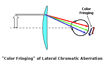 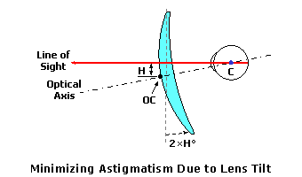 The higher the refractive index of a lens material, the slower the light will travel through it. In reality, the refractive index of any material varies slightly as a function of the wavelength. This means that various colors of light will each actually have a slightly different refractive index in the same lens material! This phenomenon is responsible for chromatic dispersion, or the breaking up of white light into its component colors by prisms and lenses. Blue light, which has a higher refractive index than red light, is refracted—or bent—more than red. Chromatic dispersion is a result of the fact that colors of light with shorter wavelengths, like blue, travel more slowly through most transparent materials than colors with longer wavelengths, like red. Therefore, blue light generally has a higher refractive index than red light. However, this is usually only a concern for certain high-index lens materials, since the differences in refractive index between colors is more dramatic. Appendix: Exact Sagitta FormulaThe mathematics described above make frequent use of the approximate formula for the sagitta (depth) of a lens surface. In reality, the sagitta of a curve actually increases slightly faster than its surface power, particularly at larger diameters. When accuracy is critical, such as for surfacing calculations, the exact sagitta formula should be applied to each individual surface. The derivation of the exact sagitta formula appears below. 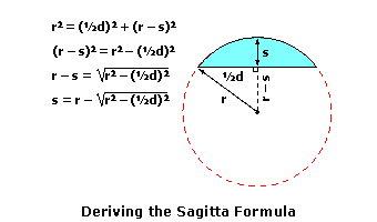 Note that this equation can be expressed (using the power ½ to represent square-roots) as: s = r - [r2 - (½ d)2]1/2 Using the Binomial theorem, and eliminating the "higher order" terms whose contributions are relatively small compared to the overall answer, gives us:
Since the radius (r) is equal to 1000 · (n - 1) / F, where (F) is the surface power and (n) is the refractive index of the material, we can substitute this expression into our equation to arrive at the approximate sagitta formula:
|
|||||||||||||||||||||||||||||||||||||||||||||||||||||||||||||||||||||||||||||||||||||||||||||||||||||||||||||||||||||||||||||||||||||||||||||||||||||||||||||||||||||||||||||||||||||||||||||||||||||||||||||||||||||||||||||||||||||||||||||||||||||||||||||||||||||

